Roll Forming Basics for Steel, Stainless Steel and Other Metals
Roll Forming Process
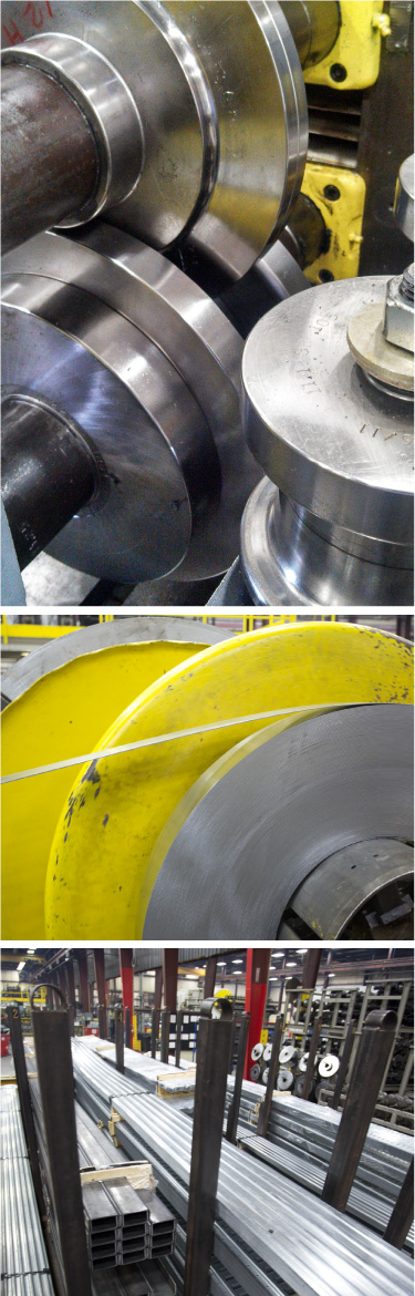
Roll forming steel is essentially a continuous bending operation performed on metal strip at room temperature. Tandem sets of rolls progressively shape the metal until the desired cross-sectional profile is achieved.
Roll forming is ideal for producing parts with long lengths or in large quantities. It can also produce parts of multiple lengths from the same tooling. Virtually any material that can be formed using sheet forming techniques can also be roll formed. Roll forming may also be an excellent solution whenever consistency of the cross-sectional profile is critical.
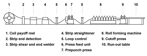
The diagram below depicts a typical roll forming line.
Benefits of Roll Forming
- High productivity rate as compared to other manufacturing processes
- Able to combine multiple manufacturing operations in-line with the roll forming stations greatly reducing total manufacturing costs
- Reduces handling, packaging and shipping costs
- Produces parts of various lengths from the same roll sets
- Able to produce parts with different hole patterns from the same roll sets
- Capable of eliminating supplemental operations (e.g. cutting-to-length, drilling, splicing, etc.)
Metals used in Roll Forming
Aluminum
Cold rolled steel
Copper
Exotic metals
Galvalume
Galvanized steel
Galvannealed steel
High strength steel
Hot rolled (and pickled) steel
Electrogalvanized steel
Prepainted
Stainless steel
Dimensions of Materials to be Roll Formed
Thickness Light gauge up to 3/8″ thick
Strip Width Up to 30 inches wide
Standard Manufacturing Tolerances
When customer specific requirements are not provided, OMCO adheres to the following Standard Tolerance Guide, relative to both roll formed parts and secondary operations as applicable.
Cross Section Tolerance
+/- .015 on decimal dimensions
+/- .032 on fractions
+/- 1 degree on angular dimensions
Part Length Tolerance
+/- 1/32″ for lengths less than 72″
+/- 1/16″ for lengths from 72″ to 120″
+/- 1/8″ for lengths over 120″
Pre or Post Punch Length Tolerance
+/- .008 per foot of length with non-random end spacing
Camber and Sweep Tolerance
1/8″ Maximum if 10′ length
Twist
+/- ½ degree per foot, can be greater in some sections depending on shape and material; depends entirely on part, radii, material, and number of passes
End Flare Tolerance
The amount of end flare is determined by material type, gauge, and sections shape. End flare can sometimes be controlled with the addition of over forming passes if necessary.